Stresses in beam due to bending is very important for an engineer. Here we are going to visualize the beam very closely to develop clear understanding.

Stresses in beam is very important topic. Every engineering graduates need to understand this phenomenon. Before understanding this we need to discuss few simple concepts.
You might have gone through this doubt while studying mechanics of solid.
"Why same member of wood or steel some time called Bar, some time Column, some time Beam or (Flexural member)?"
I am sure you might have ignored these thought. But this is very important. So, let us discuss why it is so?
A member is bar when subjected to axial tensile load (see Fig 1). It is column When subjected to axial compression load (see Fig 1). And is Beam when subjected to transverse load (see Fig 1).
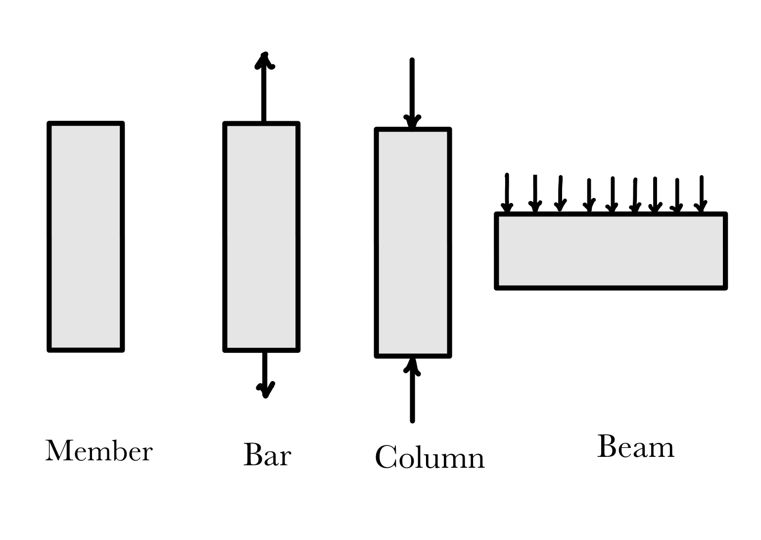
Fig 1: Member with different nomenclature
It is not the member property which governs the behavior, rather it is the type of load which governs.
We are clear now that when a member is called beam. Beams are subjected to transverse loading as shown in fig 2. Here simply supported beam is subjected to transverse uniformly distributed load. This load causes stress in beam. From here onwards we will understand the complete process of stress generation.
To resist the load, beam bends (see Fig 2).This bending causes bottom side of fiber elongate (extension) and top side of fibre shorten (compressed). These elongation and shortening is basically strains and these strains produces stress (based on constitutive relation).
This stresses results in the force (see fig 2). This force acts at centroid of area (see. Fig 2(a)). These two forces are equal in magnitude but opposite in direction, hence form couple (see fig 2(b)). This couple create resisting moment (see fig 2(c)). This resisting moment is equal and in opposite nature to the applied moment.
This is how beam resist in bending.
At this point you might have question in mind "Why beam is shown as 2D element here, in reality it is a 3D element?". You could refer to this post for the detailed discussion on this.
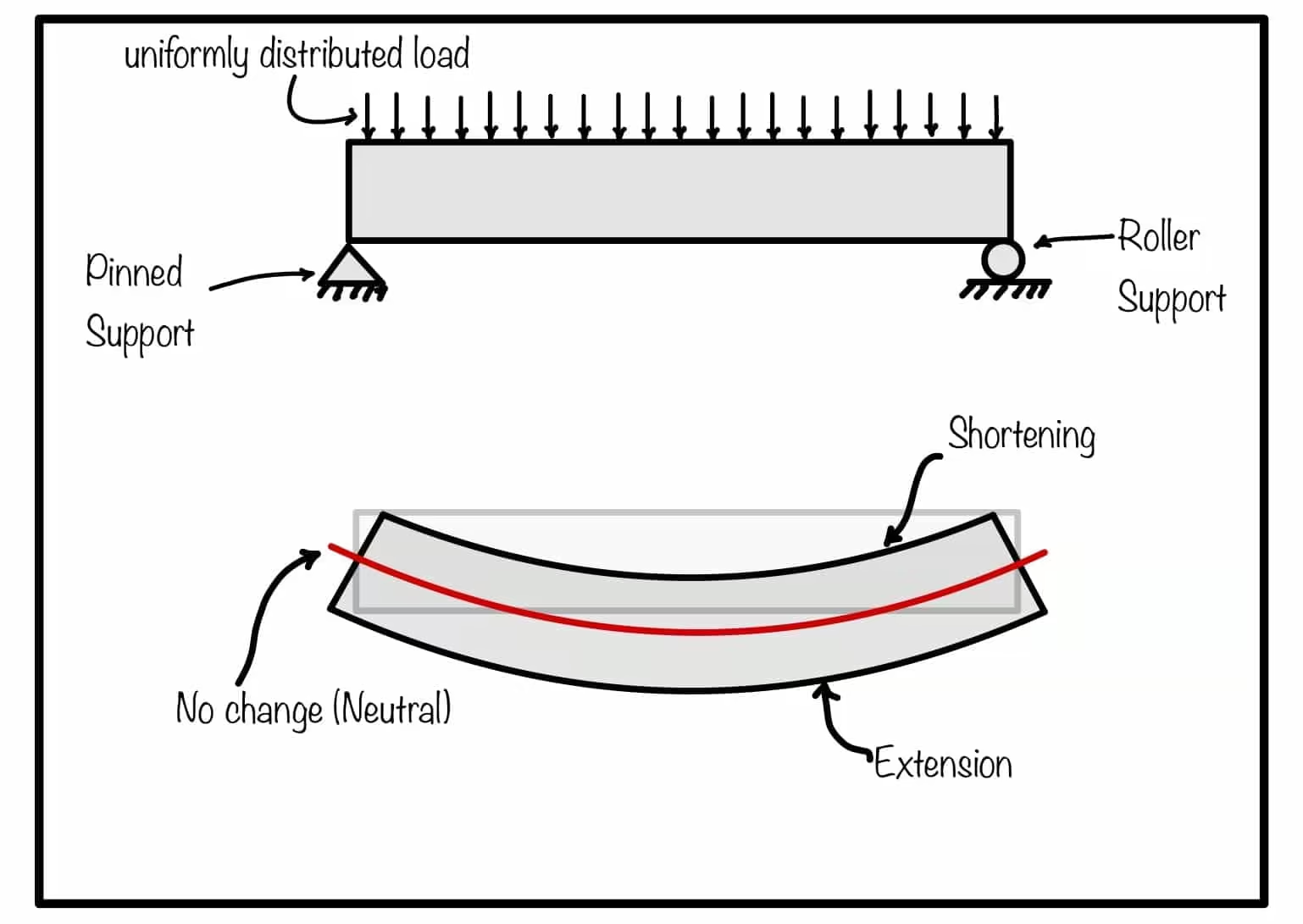
Fig 2: Bending action of beam (Flexural member)
But this is not complete picture of stresses in beam. Transverse load in the beam creates shearing effect also in beam. This shearing force causes shear stress in beam. Please refer next section for complete picture.
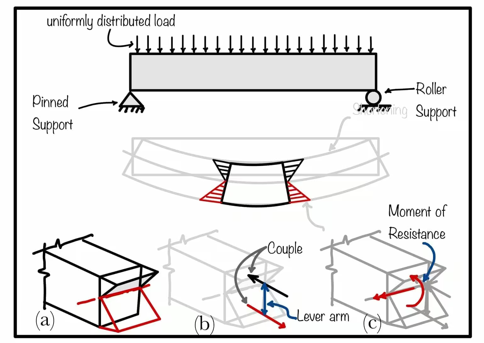
Fig 3: Generation of moment of resistance in beam section
Shearing stress is caused by the shearing action of transverse force. Refer Fig 4 part (A) which shows simply supported beam subjected to transverse loading. Part (B) represents the sectional view of the beam. In part (B) one can clearly observe the shear force in action. In part (C) we took small portion the section.
Shearing load divided by the area becomes shearing stress. This stress is acting downward as shown in Fig 4. To maintain the equilibrium equal and opposite force generated in the opposite face. These two force form the couple and produce rotation. To balance the rotation counter couple comes in picture. This force generates the horizontal shear in the beam.
This is how complete stress develops in the beam. Our objective is to quantify the stress for the design calculation. Details of this calculation is in next topic Stress quantification.
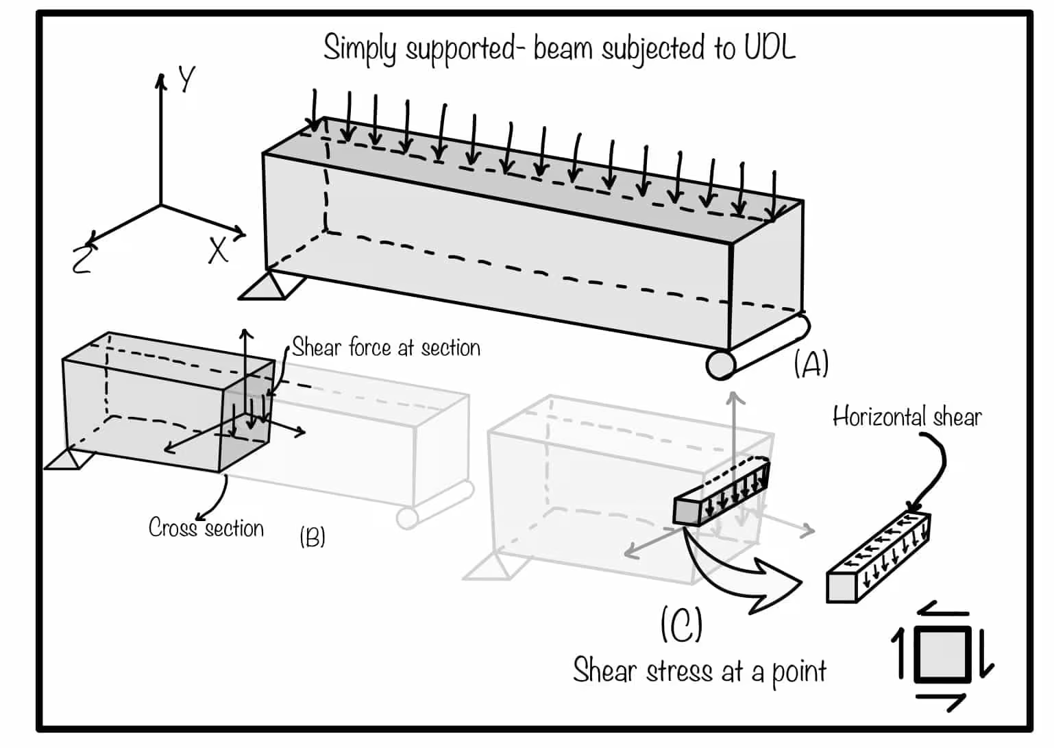
Fig 4: Explanation of horizontal shear in the beam
Your trusted source for breaking down core engineering concepts using first-principles thinking.