Shear force and bending moment diagram is the initial step to start the design process. In this article we will learn SFD and BMD.

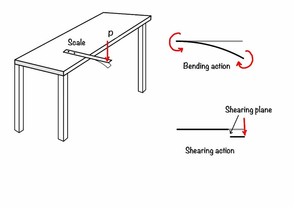
When you apply the load in the scale, as shown in the figure, you are applying a transverse load in the scale. These transverse load in the scale causes the bending and shearing effect, as shown in the figure. The force responsible for bending the scale is called the bending moment, and the force responsible for shearing the scale is called the shear force.
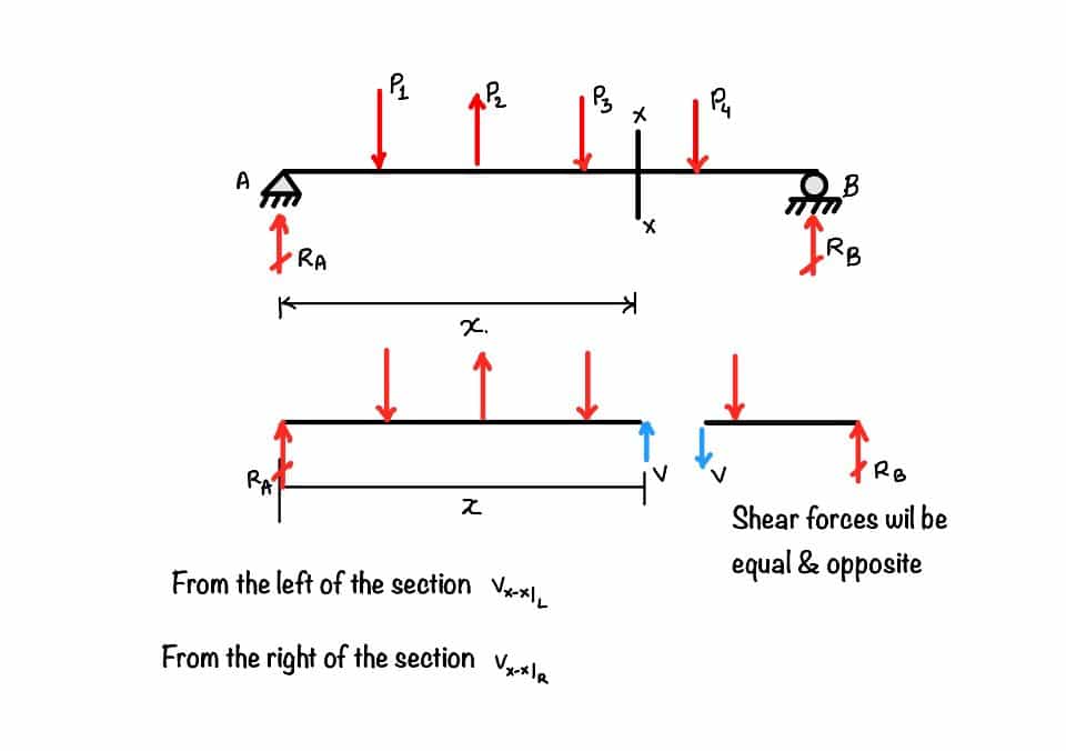
It is the summation of all the vertical forces, either left or right, of the section. You can see there is the number of forces in the beam in the figure. Suppose you want to find out the shear force at section . So the shear force at section is the summation of , or from the other side, it is the summation of .
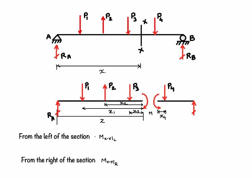
It is the summation of all the moments either left of the section or right of the section. So, for example, if you want to find out the moment at the section , then you have to add all the moments caused by the forces or the summation of the moment caused by forces from the other side of the section.
It has the basis, which one to take positive and which one to take negative, but for the time being you can take the sign convention as you wish. But the whatever you have opted that you have to follow through out the solution. Then only you will get correct shear force diagram.
So you can see the figure, there are two pair of sign conventions. If you are going through the beam in the left to right direction the all the upward forces are positive shear forces and the downwards forces are negative forces.
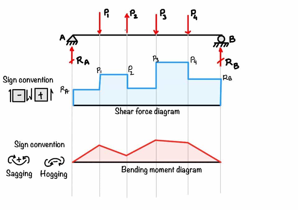
You must follow the proper sign convention to get the correct bending moment diagram. Please refer to the figure for the visualization. For example, when you are going in the beam from the left side, all the clockwise moments are considered positive, and all the anti-clockwise moments are considered negative.
This becomes the opposite when you travel in the opposite direction of the beam. That means the clockwise moments are considered negative, and the anti-clockwise moments are considered positive.
The figure shows the variation of shear force or bending moment with respect to the length of the beam. The position of the beam gives the location of the point in the beam, and the ordinate of the figure gives the value of shear force or bending moment in the beam.
These steps you will follow to draw the bending moment and the shear force diagram of the beam will never make mistakes.
Steps to draw the shear force and bending moment diagram:
Determinacy: First, check whether the beam is determinate or indeterminate. To find this, you can use the following formula:
Static inderminacy: is the static indeterminacy of the beam, is the reaction, or you can say unknowns in the shaft, and 3 is the number of equilibrium equations available for the beam. When , the beam is statically determinate.
Free body diagram: Next step is to draw the free body diagram of the beam in the problem. Like here we are doing.
Equilibrium: Now, you have to apply the equilibrium equations to find out the values of the reactions. Equilibrium equations are as follows:
Shear force diagram: After applying the equilibrium equations, you have determined all the reactions. Now next step is to draw the shear force diagram for the beam. Start from any side of the beam, and the value of forces gives you the ordinate values of the shear force diagram.
Bending moment diagram: As you have done for the beam's shear force, you must also follow similar steps in the bending moment. Show the figure for more detailed visualization.
In this post, you have learned how to draw the beam's shear force and bending moment diagram. The ordinate values of the shear force and bending moment diagram give the value of the shear force and bending moment value at that point in the bream. Next, you must find the reactions to draw the shear force and bending moment. Finally, to see the reaction, you must know the different types of supports and release conditions.
You have learned the following key points in the post:
Equation of static equilibrium: To maintain the body in the static condition is the two dimension space; you need three conditions to be satisfied. These three conditions are the equation of equilibrium.
Static indeterminacy: If the number of reactions in the beam is more than the available equation, then the beam is static indeterminate.
Shear force diagram: The summation of all the vertical forces either left or right of the section. The ordinate of the shear force diagram gives the shear force value at that point in the beam.
Your trusted source for breaking down core engineering concepts using first-principles thinking.