We have seen in the previous articles how bending stress comes in the beam and how we can find the shear stress. While deriving the bending and shear stress we considered them in decoupled manner. That means while deriving the bending we assumed that there is no shear stress in the beam and vice versa. The in practical situation bending stress mostly accompanied by the shear stress. In that case how to find the stress at a point inside the beam.
In this article we will learn how to calculate the stress at a point inside the beam when combined stress is coming due to shear and bending both.
Stress due to pure bending
If you will apply the load in such a way that it will create the pure bending in the beam. In such situations we can find the stress in the beam using the following formula:
$$\frac{M}{I} =\frac{\sigma}{y}= \frac{E}{R} $$
Where: $M$ is bending moment at that section, $I$ is the moment of inertia about the $Z$ axis, $\sigma$ is the stress at location $y$ of the beam, $E$ is the elastic modulus of the beam and $R$ is the radius of curvature.
You can find the full derivation for the bending stress in the article bending stress of the beam.
Stress due to shear force
When we apply the load in the beam, it generates the shear force in the beam. We have learned the shear force and bending moment in the beam from the previous articles. This shear force is responsible for the shear stress in the beam. The details of this can be found in the article Shear Stress. From the previous discussion, we can conclude that the following formula can give stress variation at the section of the beam.
$$
\tau=\frac{1}{I B} V A \bar{y}
$$
Where $\tau$ is the shear stress at a point, $V$ is the shear force at that section of the beam and $A\bar{y}$ is the first moment of the area of the section considered. $I$ is the second moment of inertia or moment of inertia of the section considered and $B$ is the width of at that level where we are finding the shear stress. For more detail and complete derivation of the the above formula please go to the article shear stress.
Combined stress for shear and bending stress
We have seen in the earlier articles that the bending moment generates tensile or compressive stress at a point depending upon the location of the point. It also depends on the nature of the load. The shear stress in the beam generates shear stress at a point, as we can see in the figure.

The widget above shows the stress contribution from bending force and shear force. You know the bending moment and shear force diagram for the above simply supported beam. If you have any doubt please refer to our article on how to draw shear force and bending moment.
After knowing the BMD and SFD you will agree that there are some zones where only bending force exists. Shear force is zero. Now fix the location of the point by sliding the cursor which shows the $x$ and $y$ distance.
In the zone where shear force is zero you will find that shear stress component of the point $Q$ becomes zero. Play with the widget to feel the shear stress and bending stress in the beam at a point.
Application
Stress at a point is the combined stress due to shear and bending force in the beam. This shows the state of stress at a point. This helps in finding the maximum stress at a point which is also known as the principal stress. This concept helps in understanding the variation of stress inside the beam and hence helps in making justified decision on design of the beam.
Conclusion
While we derive the stress due to shear and bending we derive them separately. But in reality they come simultaneously. Hence this condition leads to stress at a point due to combined stress.
In this article you have learned following points:
- Bending stress: We know that the bending force in the beam is responsible for the bending stress in the beam. The bending stress causes tension or compression stress at a point.
- Shear stress: Shear force in the beam is responsible for the shear stress at a point. It generates shear stress at a point.
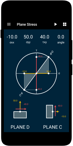
- Maximum stress: To find out the maximum stress at a point we have to use the Mohr’s circle. The direction of the principal plane is responsible for the failure of the beam.
Solid Mechanics
In this app, you would be able to explore the world of Solid Mechanics. The app covers many important topics in the field of solid mechanics.
- Interactive Mohr’s Circle of Stress and Strain.
- Calculators for Stress and Strain Analysis.
- Graphical representations of failure criteria.
- A detailed description of key concepts of Solid Mechanics with diagrams.

This article was crafted by a group of experts at eigenplus to ensure it adheres to our strict quality standards. The individuals who contributed to this article are:
Author


