Shear stress in the beam is very important for the design. This article defines and explain the shear stress in the beam.

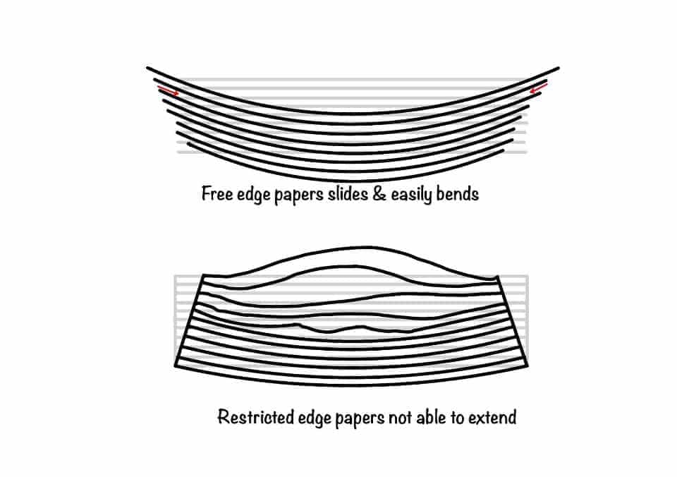
You take the bunch of papers in your hand. Take at least 100 paper than only you will able to visualize. Try to bend them, you will notice the paper slides over each other and you can easily bend the papers. Now hold the edges tightly and try to bend, you will find resistance. This resistance is due to inability of sliding of papers. This sliding will help to visualize the shear stress in beam.
In this post we will learn what is the shear stress, how it is developed, how to find the magnitude of it. We will also discuss on horizontal and vertical shear stress.
As the name appears, the shear stress is caused due to the shear force on the beam. The variation in the bending moment leads to the shear force, and the shear force in the beam causes the shear stress.
You can find the shear force at any section in the beam as the “Summation of all the force either left or right of the section.” Remember, you have to sum it up from one side. You can some it from any side and you will get the same value.
The assumption made during the pure bending formula (refer to bending stress) that the plane section remains plane is not valid here. It might remain plane, but it is not perpendicular to the neutral axis.
Before deriving the formulation, we must discuss the assumptions in the theory. Assumptions are very important in any derivation. Because assumptions set the domains where you can apply the formulation.
Assumptions in the shear stress theory are as follows:
Homogeneous: This formulation assumes that the material is homogeneous and obeys Hooke's law.
Elastic Modulus: The modulus of elasticity of the beam is equal in tension and compression.
Prismatic section: The beam is initially straight and of a constant cross-section.
The shear stress assumption as discussed in the pure bending theory, that plane section remains plane and it must maintain the with neutral axis. This assumption does not hold in present case. Plane section may remain plane but the angle with neutral axis in not .
In this section we will derive the expression for shear stress. This might look long in first appearance, but follow us step by step we will explain this in very lucid manner.
Because you want to design the beam safely, and after designing, you want to assure your client that this beam is safe. For that, you need to know the state of stress at every point in the beam. Shear stress in one which helps in doing that.
Okay, so let's start with the simply supported beam, which carries the uniformly distributed transverse load. You can refer the part (a) of the figure given below. Now consider a small section in this beam of length .
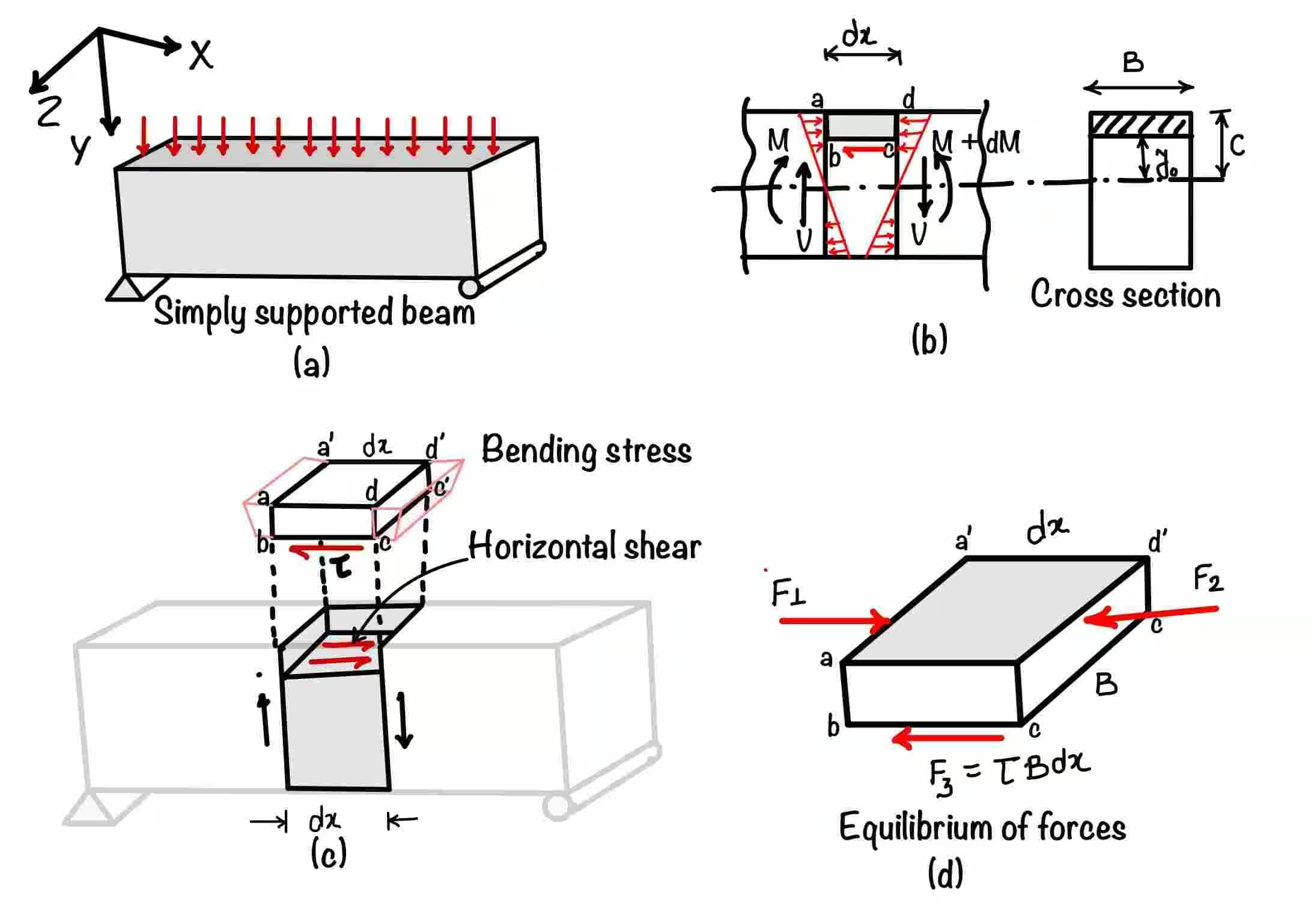
The next step is to consider all the forces acting on that portion. You will find the bending stress from the left and right sides due to the bending moments. You must have noticed that the bending moment varies. In the left face, it is , and in the right face, it is . Due to this variation, there is an unbalanced force in the small section (refer to part 2 of the figure).
Yes, you are absolutely right. The shear stress in the bottom of the shaded section acts to balance this unbalanced force. Now next step is to find this shear stress value. To find the value of that shear stress, you need to apply the equilibrium of force. Yes, you are thinking in the right direction; you need to multiply the stresses with the area on which they act.
Refer to part (c) of the figure. This image will help you calculate the area on which stresses act.
Now you have calculated all three forces acting in the considered section. The next step is to balance the equation.
Substituting the values of forces.
On solving, you will get term zero after deduction.
Where is the shear force due to varying moments, you can write the first moment of the area as . Substituting this in the equation.
This is the shear stress variation in the section of the beam.
Now we can completely understand that you are a bit confused right now. These are some questions that might arise in your mind. The shear force acts in the vertical direction, but the shear stresses come in a horizontal direction. How these are relevant. There are two types of shear stress in a beam.
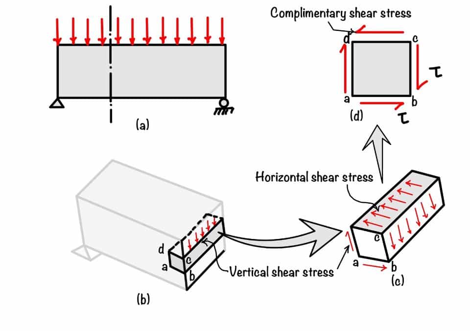
Relation between horizontal and vertical shear stress of the beam.
We have to see the figure below to understand how horizontal shear is related to vertical shear. If we take the vertical shear force acting on the beam, it will generate the shear stress, as shown in the figure. This block on one side has shear stress and will also have shear stress equal and opposite to balance the equilibrium in direction.
But these shear stresses form a couple, as shown in part (b) of the figure. And you know that block is in equilibrium. Now to balance the couple, there will be another pair of shear stresses forming an opposite couple.
Hence we hope now it is clear that horizontal and vertical shear stresses are equal.
You are now knowing the stress variation in the beam. We have discussed earlier about the bending stress, and now shear stress has been discussed. The state of stress at a point is important for design of beam. But one question may raise in your mind, that we have taken different assumption while derive the bending stress and shear stress, how can we apply them simultaneously in the beam. We will discuss this in detail in our article.
You have learned the following key concepts from this post:
Horizontal and Vertical Shear stress: Horizontal and vertical shear stress is the same in the beam. One can be derived from the other.
Specific shear stress: It,s value at the end of the beam will always be zero. At the same time, the bending stress will be maximum at the end.
Your trusted source for breaking down core engineering concepts using first-principles thinking.