Development length in beam calculation according to IS code is no longer confusing. This post explains each term very clearly with figures.

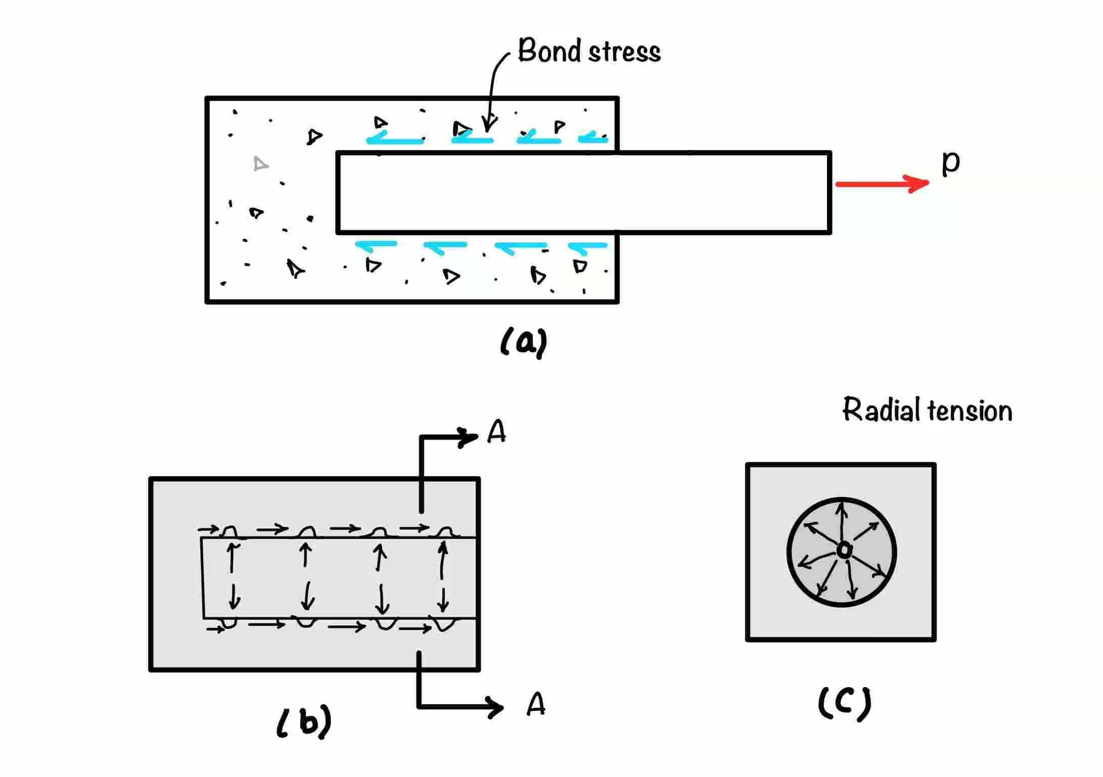
Development length is the length required to develop the grip in the rod. If you do not provide the development length to the rod, it will come out due to pulling. You need to provide sufficient length to bond stress so that it can develop sufficient force to resist the pull. You can see the figure below for more understanding. Here the rod is being pulled by force ‘P’, and the bond stress tries to develop the grip to resist the pull. In this article, we will see the development length requirement in beams.
You know we have to design according to the Indian standard code. For the reinforced concrete structure, this code number is IS-456:2000. This code gives the guidelines for different design parameters we must follow. So, according to this code, the development required can be calculated from the following formula.
Where: is known as the development length factor.
According to the IS code for calculating the required development length by substituting the stress value equal to . As it is the full strength that a rod can bear. For more than this stress rod will break. Hence we need not check the development length.
Here you will have to check whether the reinforcement in your design has sufficient length to develop the grip. That means you must check that the required development length must be less than the available one.
Now how to calculate the available grip length in the beam. So, according to code, you can divide the beam members into two categories.
Negative moment reinforcement
Positive moment reinforcement
You can see the negative reinforcement in the figure below. These reinforcements are provided to take care of negative reinforcement in the beam over continuous support. Generally, at least one-third of the total tension steel we provide for a negative moment at the support. We have to extend this steel beyond the point of inflection. This distance should not be less
, which is the effective depth of the beam
, Where is the diameter of the bar
That means you must calculate the above three values and select the greatest one. You have to provide the development length more than that value.
💡 For example, you got the values for the above three points as 100, 200, and 150, respectively. So, in this case you have to provide an extension of more than 200.
When you see the figure below, you will find that part (a) of the figure is supported, and part (b) shows the continuous beam. We generally extend to the same face for the continuous beam at one-third of the bar. The problem arises for the bar which we are discontinuing. So, in that case, the code suggests that the development length () required should not be greater than the development length provided. Please refer to the following equation to calculate the provided length:
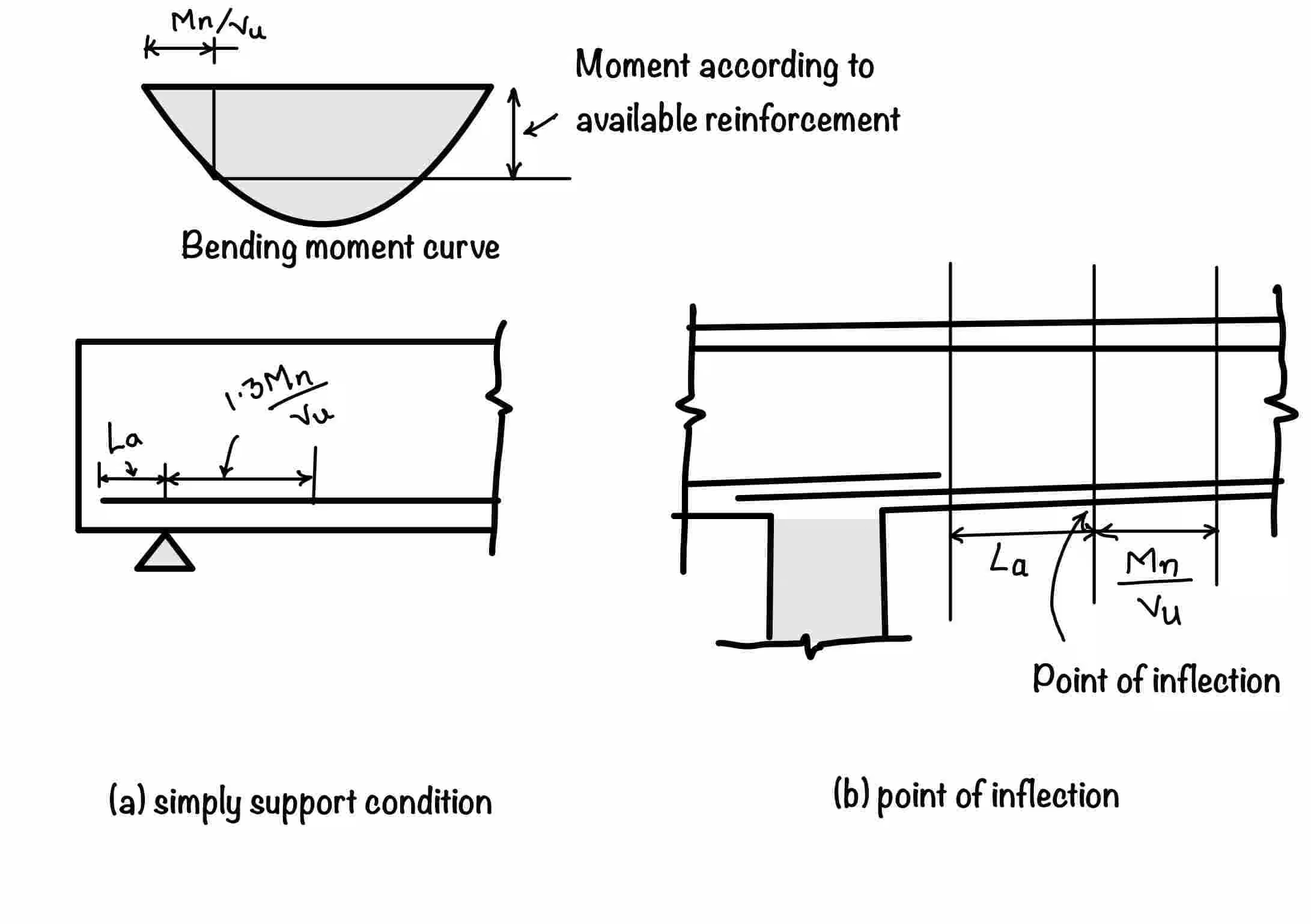
For the point of inflection, where no confinement reaction is there.
For the simply supported case, where confinement is there.
Where is the required development length, you can calculate from the equation.
You may have noticed the different terms in the development length calculation equation. Generally, many students come to us and ask for clarification. These terms seem quite confusing. In this section, we will clearly examine each and every term. We will also discuss the reason behind them.
The first part defines the required length of the bar. Which is denoted by . This you can calculate as:
Here, is the yield strength of the rod, and is the bond stress value based on the grade of concrete you can get from the IS-456:2000.
For the calculation of the second part, please see the figure. is the moment at the critical section. You remember we discussed at least of the bar you are bending up. So we need to calculate only moments due to the remaining bars.
Now, the next step is how to calculate . For that, you can consider bars are fully stressed. Now apply the moment for the remaining bars as shown below
The second term in the formula is . You can see the figure below to calculate the . It is basically an extension of bars beyond the center line of any support. It is the equivalent anchorage value at any hook. Please follow the points below for more clarification:
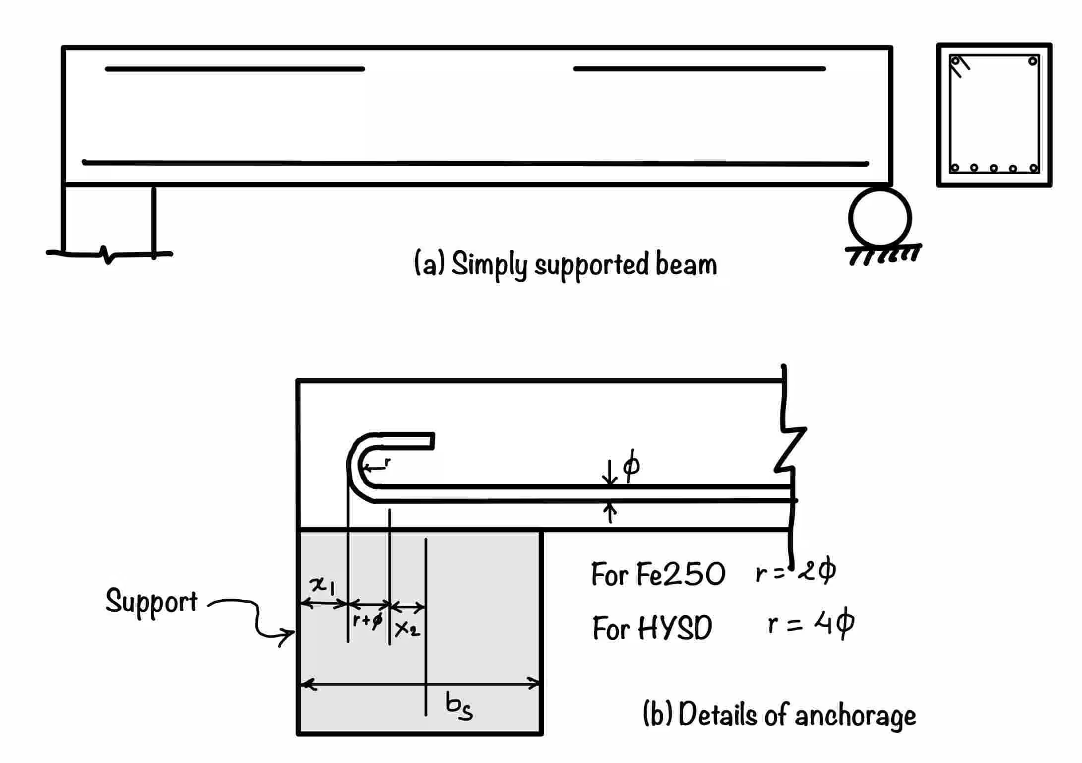
for the point of contraflexure is limited to or whichever is greater.
For bend and HYSD bars
For bend and Fe250 bars
Development length in the beam is very important for the safe design. Its calculation involves lots of confusion. Hence, in this post, we clarified each term with a diagram. Do you think you will be doing this much calculation in the field? The answer is obviously not. So for ready reference and thumb rule, please refer to the next article “Development length on fingertips.” You can also read for the footing.
In this post, you learned the following things:
Negative Moment Reinforcement: Extension should not be less than , , or , whichever is greater.
Simple support beam: For this condition of the beam where confinement load is acting, you should satisfy the following condition
Your trusted source for breaking down core engineering concepts using first-principles thinking.